3D Simulation -Visualization of Equipment/Tooling and Their Issues-
Automotive
We provide our customers with a range of benefits through 3D simulation with DELMIA V5 which has high versatility and compatibility in regard to robotic manufacturing equipment for welding / painting / transferring.
Effectiveness of 3D Simulation
What can 3D Simulation do?
- Verify / optimize layout.
- Study / select robots and tools (gun, handler etc).
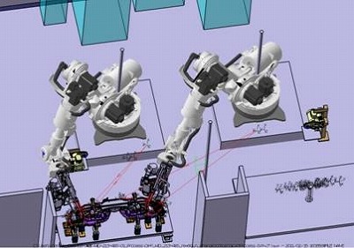
- Optimize robot movement and confirm mutual interference among multiple robots.
- Teach robots in off-line (i.e. virtual space) and transfer it into actual robots.
- Verify adding robots and changing layout for existing facilities.
- Study / select robots and tools (gun, handler etc).
- Optimize robot movement and confirm mutual interference among multiple robots.
- Teach robots in off-line (i.e. virtual space) and transfer it into actual robots.
- Verify adding robots and changing layout for existing facilities.

Effectiveness
- Visualize facilities in 3D and expose issues.
i.e. Share highly accurate image among related parties and find problems at early stage.
- Evaluate facilities with high degree of accuracy and less manpower than the methods in the past.
- Reduce number of problems caused by robots on facilities.
i.e. Eliminate issues which robots cannot access to weld points and robots interfere with parts.
- Reduce manpower and risk for work at site.
i.e. Shorten overall project schedule and improve accuracy of planning.
Process Flow of 3D Simulation
STEP 1: Collect and check up necessary information for study.
Necessary information includes Product data, Equipment conditions, Usable space etc.
Input
- Product data
- Robot specifications
- Production conditions
- Facility specifications and conceptual drawings
- Usable space
- Tool drawings
- Equipment drawings for reference. etc
- Product data
- Robot specifications
- Production conditions
- Facility specifications and conceptual drawings
- Usable space
- Tool drawings
- Equipment drawings for reference. etc
STEP 2: 3D modelling and layout study. - Design 3D layout and select tools.
Output
- 2D & 3D Layout
- Tools studied and selected
- 3D modelling data
- 2D & 3D Layout
- Tools studied and selected
- 3D modelling data
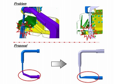
STEP 3: Simulation 1 (before detail design)
- verify robot access, expose interference and determine requirements for equipment design.
Output Example
- Results of robot access analysis and process feasibility verification.
- Various problems found and suggestions for countermeasures.
- Layout that robots arranged at the most suitable position.
- Requirements for detail design of equipment / tooling.
e.g. Provide product data including spot weld gun for equipment / tooling design.
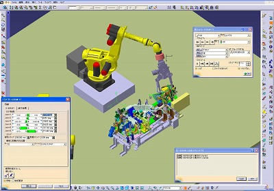
STEP 4: Simulation 2 (after detail design)
- Verify production facilities and evaluate cycle time to optimize robot movement.
Output Example
- Proposal for facility modification to optimize robot movement.
- Verification of cycle time.
- Video data as the result of simulation.
- Off-line teaching program.
(We also transfer the off-line teaching program into actual robots and correct the teaching program.)
- Proposal for facility modification to optimize robot movement.
- Verification of cycle time.
- Video data as the result of simulation.
- Off-line teaching program.
(We also transfer the off-line teaching program into actual robots and correct the teaching program.)
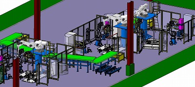
We offer 3D simulation in various cases not only for introducing one robot but also studying large volume of new production line facilities.
We can verify your equipment based on 3D cad file provided by you and study to upgrade your robots / facilities. Please contact us at any time should you have any requests for 3D simulation.
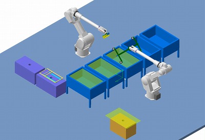
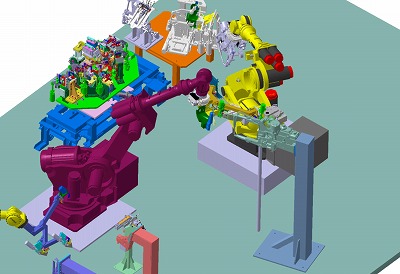
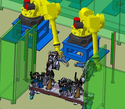
Practical Examples
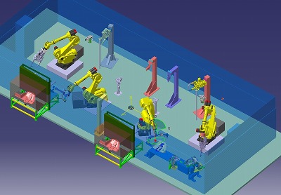

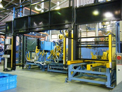
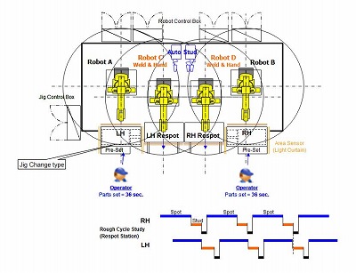
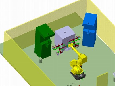
Verified production facilities with multiple robots
Process: Spot welding → Material handling → Stud welding
- Realized cost reduction and space minimization by studying equipment commonization.
Process: Spot welding → Material handling → Stud welding
- Realized cost reduction and space minimization by studying equipment commonization.
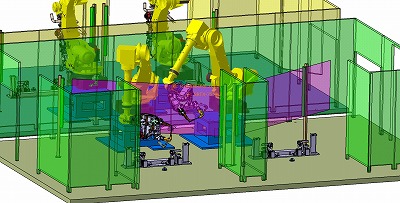

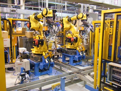
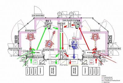
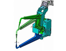
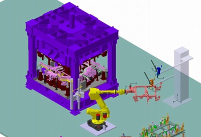
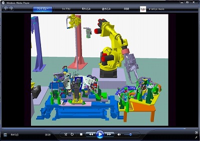
Studied if new vehicle model can be introduced into the existing robot cell
Process: Spot welding
- Verified mutual interference & sequence of movement and optimized robot motion.
Process: Spot welding
- Verified mutual interference & sequence of movement and optimized robot motion.